Really appreciate the photos, everyone. Thank you.

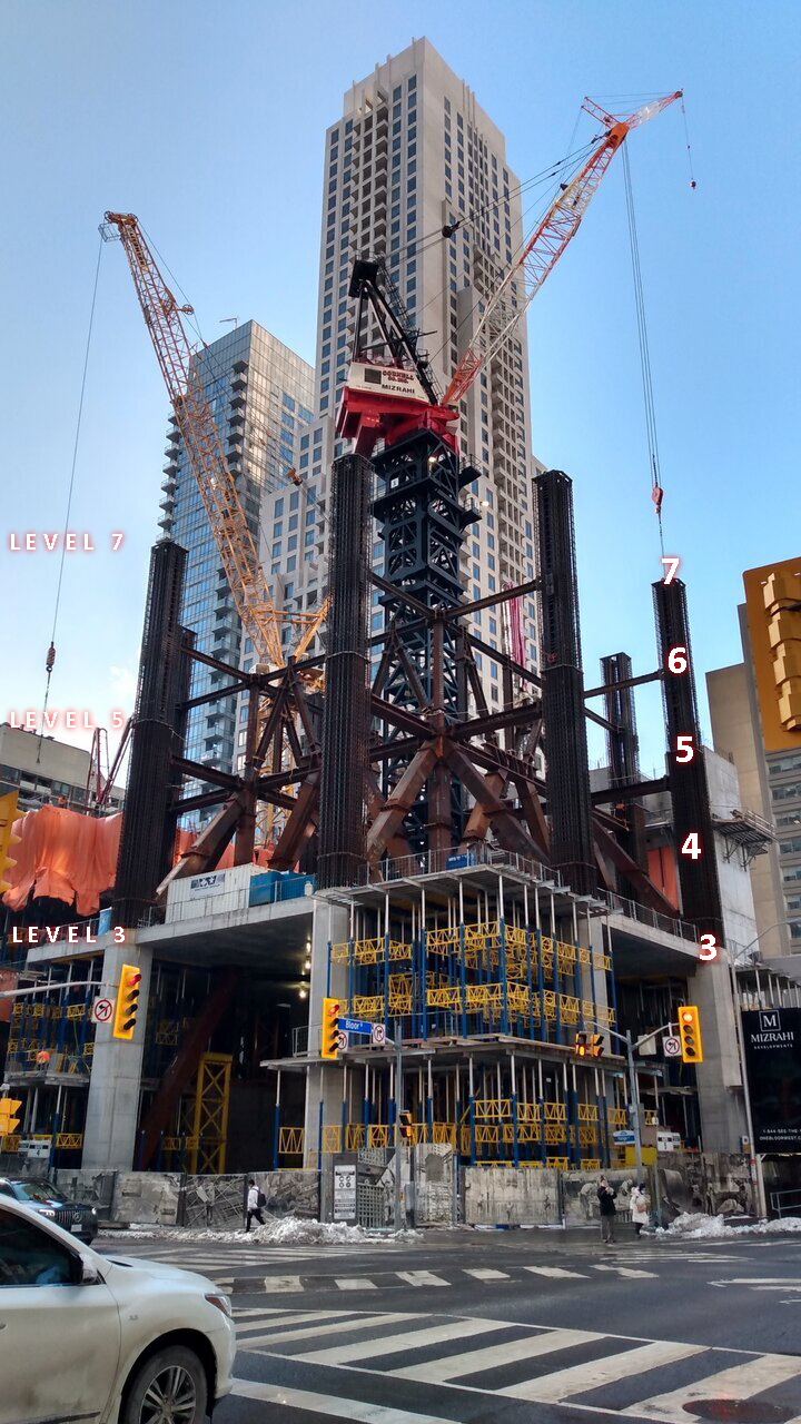
Im noticing the way the mechanical floor is being constructed might not line up with the rendering. The rendering shows the mechanical missing the corners of the building, while in the photos above, the floor corners seem to have been poured. Have a look in thaivics first two photos, the floor corners in the mech section just above the blue walls are what Im referring to.

Just above those should be the next habitable floor (you can see the support for the next diagonal beam sticking out of it.)
Has this been the plan for a while? Is it reflected in the arch. drawings?
There is like 30 feet of cornerneless space there?
 
Really appreciate the photos, everyone. Thank you.

Im noticing the way the mechanical floor is being constructed might not line up with the rendering. The rendering shows the mechanical missing the corners of the building, while in the photos above, the floor corners seem to have been poured. Have a look in thaivics first two photos, the floor corners in the mech section just above the blue walls are what Im referring to.

Just above those should be the next habitable floor (you can see the support for the next diagonal beam sticking out of it.)
Has this been the plan for a while? Is it reflected in the arch. drawings?

I don’t think so. It is hard to see the details in the photos and I could be wrong but what you see are the corner pieces for the floor above the mechanical section (floor 19) and what you see on the 17 and 18 floors are just the forms to support the 19 th floor corner sections.
 
I hope I am wrong, those cut out corners are great. Heres something to illustrate what Im referring to.

red = diagonal beams placement
green = height of mechanical section

That floor like slab thing is in the middle of the mech section. Hopefully @khaldoon is right and that is just temporary to support the upper floor until the diagonal bean can be mounted.
(photo credit: @thaivic )
mech..jpeg
 
Last edited:
I hope I am wrong, those cut out corners are great. Heres something to illustrate what Im referring to.

red = diagonal beams placement
green = height of mechanical section

That floor like slab thing is in the middle of the mech section. Hopefully @khaldoon is right and that is just temporary to support the upper floor until the diagonal bean can be mounted.
(photo credit: @thaivic )
View attachment 470300
I was thinking the same thing when I saw the photos. Maybe they are just supporting forms but they certainly look like poured floors to me too.
DD34C331-B115-4C6B-BFC6-FE7A1B43B283.jpeg
 
I was thinking the same thing when I saw the photos. Maybe they are just supporting forms but they certainly look like poured floors to me too.
View attachment 470302
My (as always) very uneducated guess, is that those supports are made for 1-floor increments. But for the Mech. sections, they just stack a couple floors worth of supports in the spacing. No floor being poured, just how the supports are made.

Again, I am just a guy with absolutely no formal knowledge on this stuff.
Yea, I had a better look and I’m pretty sure they’re not floors, just supports for the mechanical floor. let’s wait for the reveal. I’m excited to see the finished look of these mechanical floor transitions.
 
Yea, I had a better look and I’m pretty sure they’re not floors, just supports for the mechanical floor. let’s wait for the reveal. I’m excited to see the finished look of these mechanical floor transitions.

It does appear to be temporary scaffolding. IIRC the first mechanical level is also where the protective canopy will be installed to allow the base of the building to be occupied as the building progresses.
 
It does appear to be temporary scaffolding. IIRC the first mechanical level is also where the protective canopy will be installed to allow the base of the building to be occupied as the building progresses.
The second pic down in this UT article shows how they did their first corners in a similar fashion...

 
Actually, several times a week. They were there today for example.

They probably do 4 pours a cycle (floor, columns and walls, mid floor pillars, corner sections of lower floors) in addition to pouring the lower core floors through the moving central platform. If a cycle takes ~ 1.5 weeks you are looking at 2/3 times a week where cement trucks would be on site.

But this a common occurrence in most Toronto downtown neighbourhoods ( and Mississauga city centre too) so it is like living in a house that is perpetually being renovated 😊
 

Back
Top